← All four projectsProject notes

Converters

A mentor-supported comparison of commercial buck converters, their operating assumptions and loss calculations.

NOTE
Converters

I can finally ask a better question than “which one is better?”

I can now give a more useful answer than one winning converter name. The XL4015 and MP2307DN are commercial chips with different off-state paths and nominal switching frequencies. The XL4015 example uses an external diode; the MP2307DN controls a low-side MOSFET. I can follow that difference th

·3 min read
NOTE
Converters

A converter can work and still have a heat problem

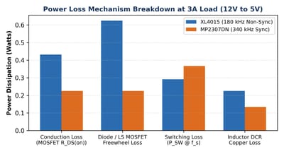
The thermal question begins inside the power calculation. The converter study separates high-side conduction, the diode or low-side path, switching loss and inductor copper loss. Those give me particular places to look for power that does not reach the load. Heat is therefore part of understand

·4 min read
NOTE
Converters

The note I want to find when I reopen this project

A value in microhenries is not a complete converter note. It needs the question that produced it. The report gives a useful example of why: the benchmark heading says 12 V down to 5 V at 3 A, but one calculation uses 3.3 V, and the ripple allowances are 1.5 A and 0.9 A. Keeping only the answers

·3 min read
NOTE
Converters

One change I can actually follow: the switching frequency

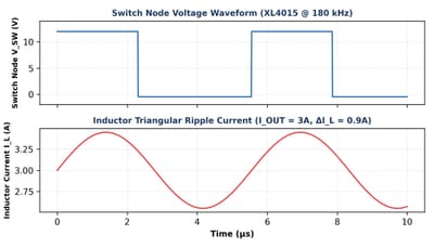
I’m keeping the ideal question fixed so I can follow one change: switching frequency. The calculation is 12 V input, 5 V output and 0.9 A peak-to-peak inductor-current ripple. With those conditions held still, the duty ratio is 5/12, and the report's equation gives about 18.0 microhenries at 18

·3 min read
NOTE
Converters

The two words beside the efficiency figure

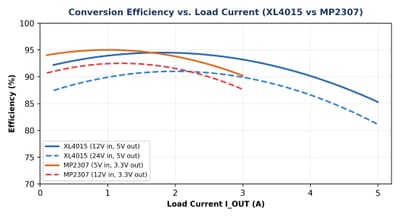
I compared the two converters on the bench and recorded peak efficiencies of 96% for the XL4015 and 95% for the MP2307DN. Keeping the input, output and load conditions beside each reading helped me understand why the percentages changed across the sweep.

·4 min read
NOTE
Converters

Following the loss through the diode

The off-state path gives me a particular place to follow power loss. In the XL4015 example, current passes through the freewheeling diode. In the MP2307DN example, a controlled low-side MOSFET conducts. The useful comparison is between a forward-voltage-drop term and a resistance term, with the

·4 min read
NOTE
Converters

The maths was fine. I was comparing different questions.

The heading says 12 V down to 5 V at a 3 A load. Then the MP2307 calculation uses 3.3 V, while the XL4015 calculation uses 5 V. The current-ripple allowances change too: 1.5 A in one example and 0.9 A in the other. Before I compare the final inductor values, I need to notice that the questions

·3 min read
NOTE
Converters

How five divided by twelve became a much bigger question

The calculation is 5 divided by 12, about 0.417. I’m using an ideal buck-converter example with 12 V at the input and 5 V at the output. The duty ratio is the fraction of a cycle for which the main switch is on. The division is easy; the reason the fraction belongs to the voltage is what I want

·3 min read
NOTE
Converters

The switch is off. The current still needs somewhere to go.

The switch turning off is where I want to keep following the circuit. In the XL4015's non-synchronous arrangement, an external diode provides a path for the inductor current. In the MP2307DN's synchronous arrangement, a controlled low-side MOSFET takes that role. The current does not simply sto

·4 min read
NOTE
Converters

Two converters that do the same job, until I look closer

I'm comparing two commercial buck converters, the XL4015 and the MP2307DN. Both lower a DC voltage, but they do it with different current paths and different nominal switching frequencies. The study gives me 180 kHz for the XL4015 and 340 kHz for the MP2307DN. Those numbers look easy to place i

·3 min read