The switch turning off is where I want to keep following the circuit. In the XL4015's non-synchronous arrangement, an external diode provides a path for the inductor current. In the MP2307DN's synchronous arrangement, a controlled low-side MOSFET takes that role. The current does not simply stop because the main switch has opened.
I find that much easier to understand when I trace a complete loop. Saying that an inductor stores energy is a start, but it leaves out the physical route through which that energy continues to reach the load. The off interval is therefore not empty time between the interesting parts. It’s a different arrangement of the conducting path, and understanding it makes the words synchronous and non-synchronous mean something I can locate in the drawing.
In the non-synchronous arrangement, the diode provides the path during the off interval. It’s often called the freewheeling path. I find the name easier to remember once I connect it to this specific job: the input switch is no longer supplying the path in the same way, but the inductor current can continue around the remaining loop. The current gradually changes; it doesn't vanish just because I have reached the word off.
During the on interval of the ideal model, the voltage across the inductor is approximately the input voltage minus the output voltage. During the off interval, its polarity changes and the current falls. I'm deliberately saying rises and falls rather than assuming it becomes zero every cycle. Whether it reaches zero is a separate question about the operating mode and the load.
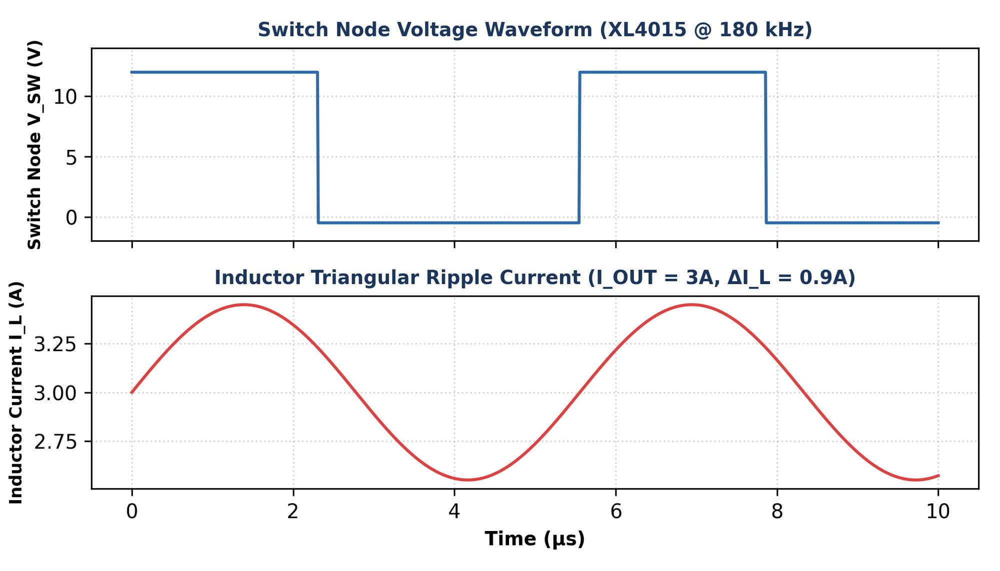
This also helps me understand the simplified current waveform. With a roughly constant voltage across an ideal inductor during each interval, the current changes approximately linearly. One section slopes upward and the next slopes downward. That's where the triangular ripple picture comes from. It isn't a statement that every real trace will be a perfect triangle under every condition.
In the illustration, the label says triangular current but the line has been drawn as a smooth curve. Looking back through that drawing, I need to keep the mismatch visible rather than use the picture as proof of what happened in a circuit. It’s an illustration, not an oscilloscope capture. The shape matters because this is exactly the part of the explanation I'm trying to understand.
The synchronous circuit has another transistor where I'm following the diode path. In this case, the low-side MOSFET is controlled to conduct during the relevant interval. I can't just imagine the two switches independently turning on whenever convenient. Their timing matters. If both provided a direct conducting route from the supply to ground at the same time, that would be a serious problem rather than a clever way of reducing loss.
That’s why I need to distinguish the simple current-path sketch from the controller's whole job. The sketch helps me see where the current can flow. The chip has to manage when its switches operate. Calling it synchronous describes the arrangement, but it doesn't save me from understanding the timing behind the word.
The loss comparison starts to make more sense from here. A diode carrying current has a forward drop. A transistor carrying current has a resistance while on. The relevant power loss depends on the current and on how long that component conducts. A part that carries current for only one interval can't be treated as if it carried the full load current for the entire time without checking the model.
There’s another detail I was leaving out: the current through the inductor isn't necessarily identical to the current flowing into the load at every instant. The output capacitor can receive some current and supply some current. Its average behaviour and its changing current are different things. This is why tracing the circuit is more useful than pointing to a single arrow and saying all the current goes there.
A helpful paper exercise is to freeze the circuit at two moments, one in each interval. I can remove the conducting path that is off and follow the one that remains. Then I can ask what voltage the inductor sees and which way its current should be changing. This doesn't need a complicated simulation to expose the place where my explanation stops making sense.
I use examples in the documentation to get unstuck on the wording, but I want the final check to be against the actual reference circuit. A generic diagram might arrange things differently from the one in front of me. If I can't identify the equivalent path, I need to go back rather than assume that recognising the same component names means it is the same circuit.
For a mentor discussion, I now have a much smaller question. I want to point to the off interval, describe the loop and explain why the current falls instead of stopping. If something in that explanation is wrong, we have a particular place to correct it. That's easier than discussing all of power conversion at once.
The current drawing is a useful check on that explanation. Its label says triangular ripple, but the line is drawn with smooth curves. In the ideal model, di/dt equals the inductor voltage divided by inductance. Roughly constant voltage during an interval therefore gives a roughly constant slope, which is why straight rising and falling sections make sense. I can use that relationship to understand the intended sketch while remembering that an illustration is not an oscilloscope trace.
What has changed is the way I read the diagram. Off no longer means nothing is happening. It means a different part of the circuit is doing the job, and the current is still following the rules I was about to forget.