← All four projectsProject notes

Power meter

A digital power-quality meter: communication, sensing, calibration and the numbers on the screen.

NOTE
Power meter

0x48

Seeing 0x48 after a blank serial monitor felt much bigger than the address looked. The controller had asked a question and something on the board had answered. That excitement is part of the project account, and the later log gives the communication result a precise record: one device at 0x48 o

·4 min read
NOTE
Power meter

Can the controller find the ADC?

The scanner asks a wonderfully small question: does anything answer at this address? In the saved program, the loop tries addresses from 1 to 126, calls Wire.endTransmission and prints an address when the returned error is zero. It uses GPIO 8 for SDA, GPIO 9 for SCL and 115200 baud for the ser

·3 min read
NOTE
Power meter

Following the voltage reading

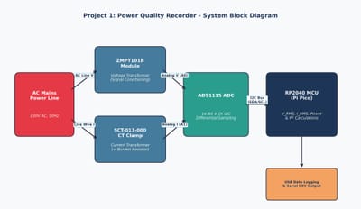
My meter's voltage path has several different kinds of information along it. The ZMPT101B module produces a signal for an external ADS1115, and the controller receives converted values over I²C. I find the drawing more useful when I follow that route instead of only recognising the boxes. The A

·4 min read
NOTE
Power meter

The explanation made sense. The board is taking longer.

GAIN_ONE is a small name with a large effect on the meaning of a reading. The saved raw sampler selects it and gives the scale as 0.125 millivolts per count. It then reads A0 and A1 separately and calls computeVolts for each. I can follow that much directly instead of leaving the ADC as a box l

·3 min read
NOTE
Power meter

Words I thought I understood

RMS, power factor and I²C are the unfamiliar terms named in my report. They no longer look like one enormous subject when I put them beside the actual programs. The scanner deals with communication. The raw sampler selects GAIN_ONE and converts counts using a stated scale of 0.125 millivolts pe

·3 min read
NOTE
Power meter

Starting with one number

The first number has quite a journey behind it. In the meter, the voltage module and current clamp produce signals for an ADS1115, and the controller receives digital readings over I²C. I like following that route because it makes the project more interesting than a screen full of values. My re

·4 min read