The socket strips are the detail I want to follow in the top-view photograph. They sit beside resistors, a capacitor and wires on the perforated board, with the soldered connections underneath. A socket joins a module to the assembly while leaving a different kind of access from soldering every module directly in place. That makes removability a useful construction question, even without a replacement incident to describe.
A socket makes a connection without necessarily making the module permanently inseparable from the rest of the assembly. That can be useful for replacement or changes. It doesn't automatically make the electrical contact perfect, and it doesn't remove the need to inspect how everything connects. I like the idea of being able to isolate a part, but I don't want to confuse removability with reliability. They are related practical questions, not interchangeable descriptions of the same thing.
I'm looking at the space around the parts as well as the parts themselves. Can I reach the connector? Is there room to handle a module without pulling at an unrelated lead? Will the part still be accessible once the other boards are in place? A layout can look spacious while it is only partly assembled and become awkward once the remaining connections are added. I want to think about the arrangement in its more complete state, rather than only the state that is easiest to place on paper.
A repair shows the issue. In this case, a module needs to be checked separately. If removing it requires disturbing several other connections, then putting everything back introduces several new questions. Did the original problem change, or did another connection move? If the module can be reached more directly, the check becomes easier to interpret. I'm using the possibility to understand why access is part of the layout, not just a convenience that can be considered after the circuit is finished.
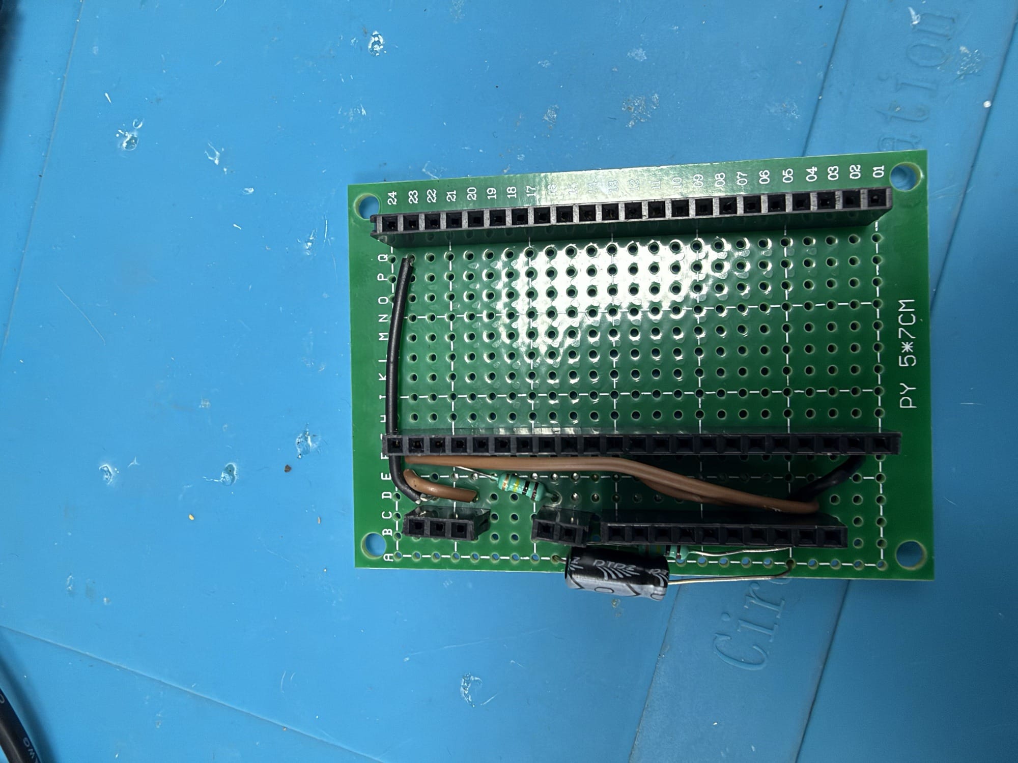
The electrical drawing and the photograph answer different questions here. The drawing can show the required relationship between points. The photograph can show how much room there is and where a socket sits. Neither one should pretend to replace the other. I can look at a photo and recognise that a board is removable while still not knowing the function of every pin. I can understand the pin relationship and still choose an awkward physical position. Putting the two views together makes the missing questions easier to see.
Orientation matters when a part can come out. Its position can feel obvious in the assembled view and become less obvious once the module and board are separate. The socket arrangement, labels and photographs preserve different clues. I can explain that relationship without turning the possibility of removal into a repair that happened. The practical task is understanding how a part fits the electrical route and what needs to stay clear when handling it separately.
I'm also thinking about labels and orientation. A removable part needs to go back in the intended way. Recognising which end faces which direction is much easier when the arrangement is clear before something comes out. I don't want the next check to depend on remembering a detail I never recorded. This doesn't need an elaborate instruction manual for every movement. A clear drawing and a useful photograph can preserve information that the assembled board temporarily makes obvious and the separated parts make much less obvious.
There’s a temptation to make the result look compact and finished. I understand the temptation because I want the project to feel like something beyond a collection of temporary connections. But a layout that photographs neatly is not automatically a layout I will enjoy working on. Leaving access can look less dramatic than squeezing everything close together. I would rather be able to follow and inspect the circuit than make its outline smaller without a reason. The arrangement should help me think, not just make a nicer top view.
The actual construction is socketed perfboard rather than a custom manufactured PCB. That still leaves real decisions about access, orientation and connecting the socket positions to the rest of the circuit. I can explain those decisions in terms of the visible arrangement without giving the board a grander name.
The sockets don't answer every question about access either. The surrounding parts and leads still matter. I want to think about the whole action of reaching and removing a module, rather than treating the presence of a socket as the end of the design decision.
The two kinds of connection also make the board easier to describe. The soldered path joins particular socket positions to the rest of the circuit. The socket contact joins a module at those positions. Thinking about them separately helps me distinguish changing a module from changing the circuit around it. A removable part still needs the correct orientation and connections; the socket preserves access, while the electrical drawing preserves the intended relationship.
The socket gives a simple question some real depth: can I keep understanding this part's place in the circuit when it is no longer sitting in it?